| ||||||
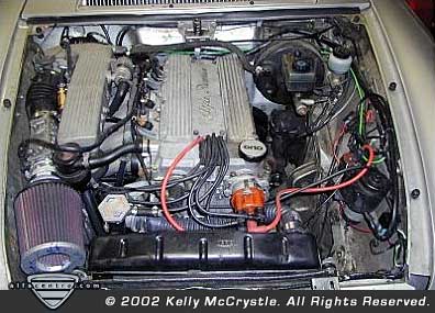
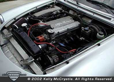
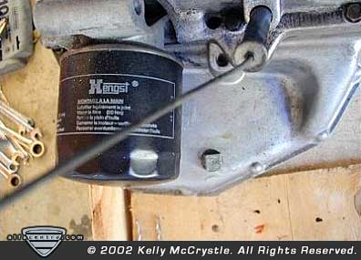
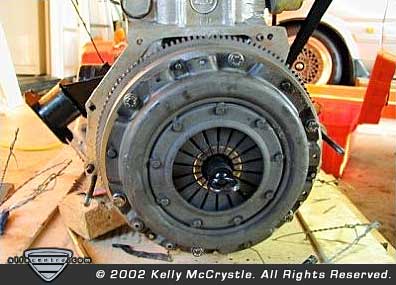
| ENGINE PREPARATION Although the engine looks like it will not fit into the Spider’s engine compartment with the stock intake manifold, rest assured it will, though it is a little tight. Lastly, I have come to find out that all TS equipped 75s that left the Alfa factory were not wired the same. The wiring harness that came with my engine was for a non-catalytic equipped car, therefore it did not contain any provisions for an 02 sensor. Also, from the factory the harness may include a “fuel quality” relay. Depending on how this relay is wired and the color of the relay will depend on how the ECU that you sourced will run the engine. This relay is located a short distance from the ECU on the wiring harness. See Appendix A for a chart of the fuel quality relay wiring. In addition to the Fuel Quality Relay there is also another connector including the wires for the on-board diagnostic functions. You will need a normally open switch and a 12V bulb to make the diagnostics work correctly. The test switch is wired on one side to the light blue/yellow and ground on the other side, the light should be wired light blue/red to Negative side and pink to Positive side. The diagnostic functions of the Motronic ECU will not work unless the engine is running. See Appendix A for the blink codes for the self-diagnostic function. OIL PAN | ||||||
| ||||||

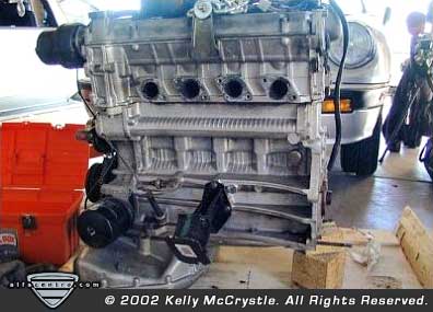
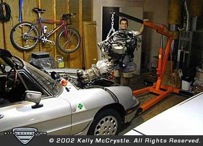
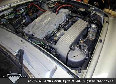
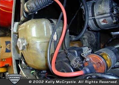
| TS ENGINE INSTALLATION WIRING HARNESS To begin the installation of the TS engine, you should first run the new wiring harness in the car. I chose to locate the ECU and the relay bundle inside the car underneath the passenger side dash. Before you remove the harness from the engine be sure to label all of the connections. You will need to separate the wires in the harness, though at this time DO NOT CUT ANY WIRES. The wires are run through a hard plastic connector located adjacent to the ECU connector. DO NOT ATTEMPT TO CUT, this plastic part is molded around the wires and cannot be removed without cutting the wires. Start from inside the passenger compartment and pass the wires through the hole in the firewall where you removed the stock L-Jet harness. You should pass the following wires/connectors through. 1. Crank Sensor Wire - Bright Green Shielded. 2. 02 sensor wire (if applicable) Bright Green or Orange 3. Coil Black with Green stripe 4. AFM -Blue 5. Injectors 4 plugs Yellow wire/ Red wire 6. Idle motor control 7. Temp Sensor 8. TPS You can refer to the wiring diagrams located in Appendix B for the correct wire connections and colors for each component. I chose to place the relay pack under the passenger seat, from the relay pack run the three red wires to the parcel shelf behind the passenger seat and connect them to the battery. You should fuse the connections with modern style blade fuses. The pink wire from the relay pack should be connected to both fuel pumps. This wire may be directly connected or you can choose to connect the pumps to a second relay and use the pink wire to switch the relay. Connect the black/green wire to a 12V switched source. This can be located on the passenger side under the dash where there is a connector located there including a black/green wire. THROTTLE CABLE You will need to convert the Spider’s throttle assembly from a linkage assembly to a cable assembly. I first tried to source a throttle assembly from a 91-94 Spider, as these were a cable driven assembly directly from the factory, though I did not have much luck in finding one. This would be the easiest way. Next, I went to the local auto parts store and located a throttle cable assembly for a Honda, I cut one end off, thus leaving me a cable within a stiff housing, one end of the cable included a fitting with an eyelet. I drilled a hold in the firewall next to where the original rod assembly connected to the pedal. I then bolted the end of the cable to the eyelet. I routed the housing and cable through the passenger compartment of the Spider and out the wiring harness outlet. You could also replace the entire pedal assembly with an aftermarket unit, such as those available for HotRods, see Street Rodder magazine for suitable pedals. ENGINE INSTALLATION After you have done all of the above it is time to install the engine. I chose to install the engine with the transmission bolted in place. In order to install this as a package you will need to remove the tie-rod connecting the two wheels or else there is not enough clearance. Jack up the rear of the car as high as it will go and support it safely. Then with the assistance of a friend, tilt and lower the engine into the compartment. Although it looks tight it will fit! Once you have the engine in place lower the rear of the car to a more workable height and again support it safely. Then place a jack under the tail of the transmission and lift it into place. Proceed to bolt up the transmission supports, drive shaft (including a new Guibo), and motor mounts. Install the starter and alternator if you did not previously. Connect the wires to the starter and alternator using the stock wiring. I installed the engine coils where the stock air-box used to be. I used the stock coil bracket from the old location. You will need to switch the two coil wires from each distributor to gain the length to connect the respective coils to the distributors. Continue to connect the remaining wires to the engine. To connect the tach, there is a brown wire from the wiring harness that connects to the coil pack, connect this to the white wire that you removed from the (-) terminal of the tach. You will need to undo the wiring harness along the radiator support to access the white wire and move it to the new location. | ||||||
| ||||||
| Neither AlfaCentro.com, it's publisher, FORZA Modern Media, LLC., or the individual article authors makes any warranties, expressed or implied, that the techniques, modifications, and procedures outlined in these stories are free of errors and omissions, meet applicable safety standards, or are suitable for the purposes described. The publisher and authors also expressly disclaim all liability for damages or injury that may arise from the use of information presented in these articles. |
alfacentro • features • tech q&a • resources • classifieds • about us • announce list